
Instructions for the Use of KY1-B Single-phase Closed-loop Flip-flops
I. overview
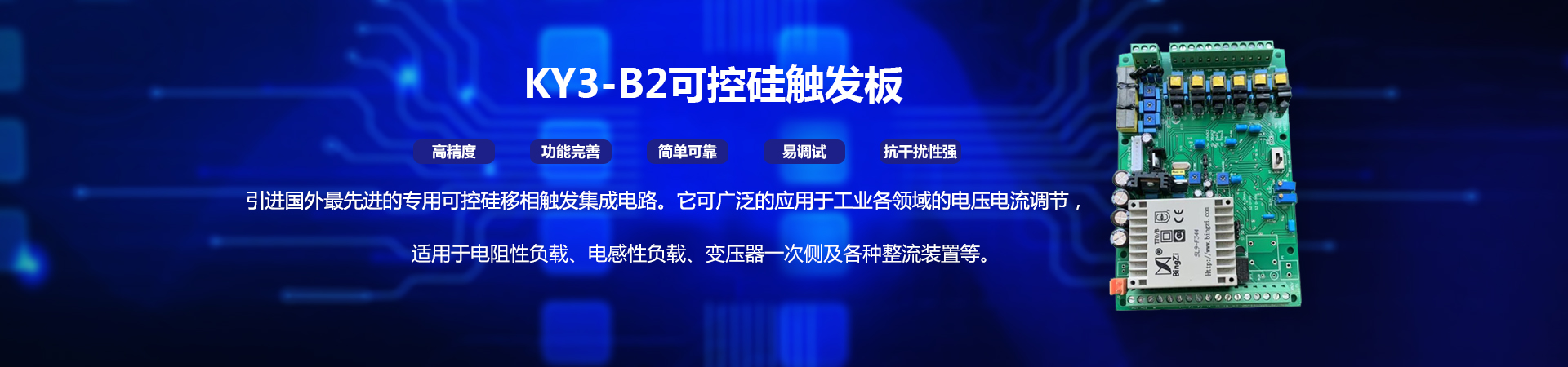
KY1-B single-phase closed-loop flip-flop is a special silicon controlled phase-shifted trigger integrated circuit imported from abroad. The output trigger pulse has extremely high symmetry and stability, does not change with the ambient temperature, and has no phase sequence requirements. It contains complete fault protection functions such as phase absence, overcurrent, overheat, etc. It has the advantages of high accuracy, perfect function, simple and reliable use, easy debugging, strong anti-interference and so on. It can be widely used in voltage and current regulation in various fields of industry. It is suitable for resistive load, inductance load, primary side of transformer and various rectifier devices. It is mainly used in high-power power supply, AC and DC voltage regulation, salt bath furnace, power frequency induction furnace, quenching furnace, temperature heating control of molten glass and various industrial furnaces; rectifier transformer, power dispatcher, primary side of electric furnace transformer, magnetizing and demagnetizing regulation, DC motor speed regulation, single-phase motor soft-start energy-saving device; with nickel, ferrochromium, far infrared heating elements and silicon-molybdenum rod, silicon. Temperature control of heating elements such as carbon rods, etc.
Ⅱ. Performance characteristics
○ The requirement of phase-disorder is limited. It can be used in power supply of 220 V and 380 V power supply frequency of 50/60 Hz power grid.
○ It can directly interface with the output signals of various control instruments (temperature controllers) and microcomputers at home and abroad.
○ It is suitable for resistive load, inductive load, primary side of transformer and other load types.
○ It has soft start and soft stop function (adjustable start time), reduces the impact interference to the power grid, and makes the main circuit more safe and reliable.
○ Driving power is strong, each circuit can output 800 mA of current, can drive 4000A thyristor.
○ Fault alarm output function. (External buzzer and indicator)
○ Urgent stop function.
○ 0 Voltage limiting function.
○ Overcurrent and overvoltage protection function end.
○ Temperature control and protection function end.
○ With full-pass function control terminal.
○ Open-loop and closed-loop control modes and two pulse operation modes are applied to different loads.
○ Integration structure: power supply, synchronous transformer, trigger control circuit and pulse transformer are integrated. Structural tightness, easy debugging, simple wiring.
Ⅲ.Main Technical Indicators and Their Use
Input signal: 4-20mA (short connection S1 is selected by P1 jumper) DC 0-5V (short connection S2 is selected by P1 jumper) DC 0-10V (short connection S3 is selected by P1 jumper) 10K potentiometer (manual adjustment)
Output Specification: Single-phase or two-phase two-way trigger 0-100% output.
Phase shift range: 0-180.
Trigger capacity: <4000A thyristor.
Indicating function: DS1_PC board working power supply indication
DS4 Failure Indication (OFF)
Power usage: AC1 and AC2 are connected to 220V or 380V main power supply. When inputting 380V main power supply, be sure to select input through JP11 jumper, otherwise transformer will be damaged (220V input is selected when leaving the factory).
Load test: SCR can not work properly without load or current less than 0.5A when testing trigger. So the load current should be greater than 0.5A.
IV. Working methods
1. Open-loop or closed-loop operation modes.
○ The trigger chooses open-loop or closed-loop mode through JP10 jumper. When debugging triggers, it is better for users to choose open-loop mode to debug. If open loop is used, please choose jumper to connect KH with BH (refer to wiring figure 1).
○ The flip-flop can access AC feedback signals of current 0-100mA and voltage 0-50V for AC constant current and voltage control. (Users can use JP1, JP2; JP8, JP9 to select mA and AC for AC closed-loop control mode)
○ The flip-flop can be connected to shunt 0-75mA and partial voltage 0-30V DC voltage feedback signal for DC constant current and constant voltage control. (Users can use JP1, JP2; JP8, JP9 to select mV and DC for DC closed-loop control mode)
○ Flip-flops can be sampled according to different requirements. The trigger can also form an external closed-loop automatic control system with a single-chip computer and corresponding detection sensors.
2. Three input modes can be selected:
○ 4-20mA input. Short connection S2 and S4 are selected by jumper combination.
○ 0-10V input. Short connections S1, S4 and S5 are selected by jumper combination. (S5 not short connection 0-5V control)
○ 0-5V input. Short connections S1 and S4 are selected by jumper combination.
3. Soft Start Soft Stop Function:
When the trigger works in open-loop mode, the soft start and soft stop can be controlled by choosing short S3 through JP4 jumper. Soft start time is set by adjusting VR2 (RQ) variable resistance; soft drop time is set by adjusting VR3 (RJ); and starting voltage value is set by VR6 (QU).
4. Voltage limiting control function:
The flip-flop can limit the input voltage by adjusting the variable resistance of VR1 (VCON).
5. Overcurrent and overvoltage protection function:
The trigger is connected with current feedback signal and voltage feedback signal. Overcurrent (GL) protection and overvoltage (GY) protection are selected through JP13 jumper.
6. External protection switch: External temperature control protection switch (reference control wiring diagram).
7. All-pass function (ON function):
Normally close this switch SCR is full-pass output and normally open to normal working mode (refer to control wiring diagram control).
8. Pulse Forbidden Output (OFF Control Switch):
The trigger can be controlled by an external switch.
9. Two pulse control modes:
The trigger can choose two different output pulse modes through JP12 jumper, which can be more effectively applied in different working situations.
V. Exclusion of Abnormal State
1. When the input control signal is small, the SCR is close to 100% output.
○ It is possible that the flip-flop has no feedback signal in the closed-loop mode, which results in the incorrect judgment of the integral system of the flip-flop. Please access the closed-loop feedback signal.
○ The load current of flip-flop in closed-loop mode is too small.
○ Check whether the feedback signal is connected correctly.
2. SCR has no output, no current or voltage:
○ The panel DS1 indicator is not on and the SCR cannot work. Please check whether the power supply of the trigger is connected correctly.
○ Check whether the DS4 indicator is on. If it is on, please check whether the protection system and synchronization signal are connected.
○ Check whether RES switch is short connected.
3. Trigger users can not solve the problem, please do not hesitate to contact our company, we will solve it for you in time.